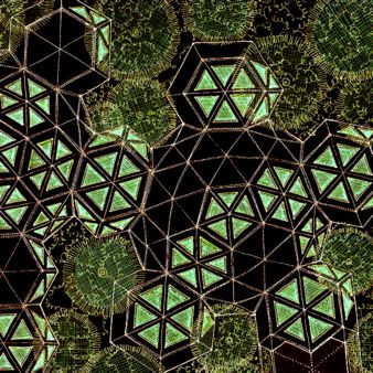
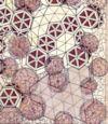
Hexipent
Geodesic Dome cluster - 1979
Night view |
| The
dome offers great promise along with a set of serious
design challenges. One of these is how to bring it
gracefully to the ground [link] -
another, is how to utilize the basic round shape
- which works well for some functions
but not for others - in the creation of buildings
that require multi-functional spaces. |
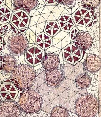
| The
drawing, above, is from a 1979 project exploring
how the Hexipent geodesic dome configuration, developed
by Bucky, could be used for prefabricating modest
scale,
light
weight, movable buildings. The dome is built in hexagon
and pentagon segments that are shop built and assembled
on site; thus, the entire superstructure is made
up of a few easy to handle pieces that can be erected
in
a day or two. A standing seam flashing and counter
flashing system between these segments facilitates
quick waterproofing.
Recently,
a project
in China [link] -
one of much larger scale and higher technology, than
shown here, - used the hexipent configuration
as a basis for prefabricating components. |
| I
call this dome design the “snowflake” configuration.
Usually, a dome of this type (low-tech, employed
as home or small office use) will meet the ground
with a series of half hexagons where doors and windows
are usually placed. This is awkward and ugly - the
forms do not work together any more than carriage
lanterns
would
be
right on
a modern
automobile. This
configuration also fails to provide adequate height
for a comfortable two story layout with domes of
modest
size.
There
are thousands of such low-tech geodesic domes that
fail to meet the promise of open space and who squat
uncomfortably on the Earth and enjoy multiple waterproofing
problems. |
| In
this design, the pentagons sills are 3 feet above
the grade and, in each half-hexagon, a horizontal
hexagon roof segment forms a space off the main dome
area - 5 per dome. This provides small rooms, entry
areas, connection segments to other domes. It allows
a more friendly meeting of the structure to the ground.
In the illustration shown, berms come up to the dome
structure sills. This provide the head height necessary
for the hexagon areas and makes the dome, itself,
high enough for a second level under the higher parts
of the dome. Inside, this provides three foot vertical
walls (below each non-opening hexagon and pentagon)
useful for built-ins and furniture docking. The berm,
on the outside, keeps the profile of the structure
low and bridges between structure and ground with
landscaping. |
| One
idea of this project is that buildings for temporary
use can be set up quickly almost anywhere. These
can be used for schools, display and meeting facilities,
offices, housing - what have you. As example, if
we were to do an RDS [link] where
no space was available, a complex like this could
be set up in the parking lot of a hotel or shopping
center - even an open field [link]. |
| The
structure can be erected (one day) the berm structure
put in place using planter boxes and potted plants
(one day; see: EcoSphere Greenhouse [link])
and a level floor of brick over sand provided for
the interior
spaces
and the
patios
(one
day).
There would, of course, be no berms at the entries
and patios. Any number of domes and hexagonal rooms
can be provided in numerous configurations as required.
Power, communications and waste management are provided
in prefabricated self-contained unites that “plug-in” the
hexagonal configuration. Properly done, a building
like this can work for months with little or no maintenance
required. Because the building is light weight -
and the weight is so evenly distributed - the structure
will easily sit on whatever paving, gravel or compacted
earth that exists. Once this shell is set up, complete
with windows and doors, interior components are moved
in (two days). |
| For
installations of greater duration on unpaved ground,
wood foundations can be employed. An alternative
is to put the entire project up on a modular wood
platform, a prefabricated concrete footing, even
compacted earth or straw bale construction - or any
combination of these design strategies. Whatever
foundation and base wall treatment is used, the idea
is cause minimal disruption of the terrain (or built
site) and maximum
reusability of all materials. |
| The
interior layout would use the same kind of set up
of a typical AI/MG
Taylor environment [link] with
the domed areas used for large flexible work areas,
the hexagonal rooms
for more intimate, private spaces and the lofts for
sitting and reading areas. |
| The
dome and hexagonal room components are built of plywood
over wood and steel frames and provide a combination
painted and wood finish on the exterior and interior
- much like a wooden boat. The windows-skylights
are mostly in the hex shapes making most of the view
up and out and into the landscaping areas. Entry
doors, opening into patios, are made of wood and
glass to provide horizontal views into the contained
patios. In general, the language of the a typical
Usonian [link] is
employed. The interior spaces are large circular
domed rooms with the smaller hexagonal rooms with
lower ceilings (see: Schematic layout below). Second
level platforms are optional. The skylights-windows
can be placed to best make good views and appropriate
natural lighting. These windows-skylights have built-in
shades (see below) for control of view and light
levels. There is no compromise with this approach
between utility and architectural values. Most Pattern
Language [link] values
can be accomplished. |
|
|
| The
EcoSphere [link] project
uses the same dome configuration but employs a different
site strategy than what is described here. |
|
| In
all, great freedom of layout is accomplished that
provides the flexibility to make extremely useful
arrangements as may be required by many different
uses of the building. The entire structure can be
reconfigured if necessary. The nature of the structure
and the way that it is built creates a composition
of great strength. The structure is anchored to the
pavement or ground with steel pins which are removed,
and the holes filled, when the building is taken
away. |
| The
exterior finishes and waterproofing can be engineered
to last, at least, between one year and 18 months
without field work. In between deployments, the surface
skins will be be refurbished - as a boat is on haul-out.
This is likely a 30 day cycle at most. |
| The
cost of deployment will be about 10% of the capital
value of the structure which, itself, will be low
compared to many other systems. This deployment strategy
is practical in circumstances requiring time-to-value
compression [link],
when transportation is critical and/or when demand
ebbs and flows. It also readily
facilitates temporary use of land that is in “holding” waiting
development. This concept of temporary development and
staging the development of land through an economic
cycle based on its urban context has long been a
factor of our real estate development philosophy
[link]. |
| It
should be clear that the same thing can be accomplished
on undeveloped ground - the siting strategies would
be somewhat different. |
| This
system provides an attractive, useful, flexible,
movable structure that will last for years as it
is deployed from site to site - one that exploits
the feature of the geodesic dome while mitigating
its few but serious downside characteristics. |
| This
can make you wonder why “permanent” building
are so prized - and it should. In future years, the
distinction between “buildings” and “vehicles” will
fade. We will discover that buildings have to adjust
to site and circumstances in a far more adaptive
way then they do today - and, that vehicles are environments
that have to support more kinds of activities than
sitting on an uncomfortable bench, unable to work or relax,
while passively watching the world go by. |
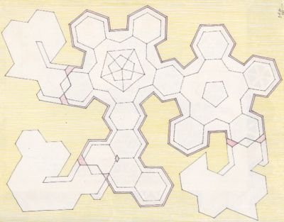
Typical “Snowflake” cluster
of
two domes and pod units
|
| The
schematic layout above shows the diversity of space
possible with this configuration -it is a space rich
in both prospect and refuge. A high variety of functional
areas can be accomplished. This drawing
is oriented the same as the partial top view (but
is reduced in scale). The domes, using plywood construction,
can range in diameter from 50 to 75 feet making the
Pods about 15 to 20 feet across. The layout shown
has three Patios, three Entry/Exits, two domes (one
with a loft area) and 6 private Pods. In addition,
7 Pods are used for circulation and transition uses. |
| It
should be clear that this same kind of configuration
can be used for domestic living space or a combination
of domestic and office. Even small shops can effectively
employ this kind of configuration. |
|
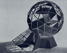
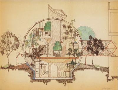
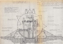
Addition
to traditional house - July 1973 |
| In
addition to how the dome rests on the site there
has been few uses that properly treat and fully make
use of the interior space. In addition, getting in
and out of the structure (gracefully), and fitting
in with traditional buildings, has been a chronic
problem with this structure. Another design problem
is “fitting” the dome to more traditional
structures. The Section above shows some design strategies
for dealing with these intrinsic problems: |
| Surround
the dome with a landscaped earth berm that
intersects at the 2/3 curve plane of the
dome - this joins the dome gracefully to
the Earth and provides a landscaped band
around the structure. This landscaping can
be ornamental and eatable as is appropriate.
Exact view points and privacy (view and sound)
can be achieved with proper plant location. |
| Build
a central core that houses mechanical systems,
plumbing, fireplaces and electrical, vertical
movement aids (stair, elevators, etc.)
- penetrate the dome following the shape
of one geodesic “hexagon.” No
other penetrations (other than the entries)
will be required. This takes advantage
of the dome’s waterproof skin and
maintains it’s integrity. From the
horizontal center line of the dome, build
a bridge (open or closed is optional),
again following a “hex” shape.
This should be designed to fit the second
level of the traditional building (or other
entry portal). In domes of greater size,
it can be useful to provide and underground
entry [link] tube for security and esthetic
reasons. In the case of the dome shown,
which has a partially underground floor
level, build a descending stairway through
one portion of the earth berm. Now, the
two structures are connected and integrated
but visually isolated with landscaping
softening the negative space between their
two forms. |
| Cantilever
all the living space floor platforms off
of the central core and avoid contact with
the skin of the dome - leave this free
to be expressed as an “environment
valve.” This way, the geometry of
the floor platforms is “resolved” by
the negative space between the dome geometry
and the platform’s. There is no way
that these can be resolved with contact
- a series of ugly, difficult shapes, expensive
to build, is the inevitable result. Design
privacy into the layout by the vertical
and horizontal location of function spaces
(going from “public” areas to
more private and so on). |
| Design
the solid and glassed sections of the dome
with attention to sun and views. Light
the inside from the outside thought these
glassed areas which will provide shadows
at night, like in daytime, and enhance
a sense of privacy without having to pull
the shades. Note that “unusual” viewpoints
can be provided by this schema as shown
on the section Traditional building hold
viewing too much to the horizontal orientation,
looking out “up” and “down” opens
the mind [link] to
new experiences. |
|
In
the illustration shown, there are several levels including
a underground floor and platforms. The underground
level is the greenhouse, kitchen and informal eating
area. The next level up, the Entry, Living spaces and
formal dining areas (food comes through a vertical
lift which is a warmer). The platforms, above, are
sleeping and private work areas. Of course, in this
case, there is some program integration with the traditional
building to which the dome is connected. |
| The
dome shown is 25 feet in diameter. The useable space
is the entire sphere. The full potential dynamics
of the shape are used to the maximum and the usual
problems associated with a dome (conflicting geometry’s,
pie shaped rooms, stuff penetrating the dome at awkward
places and other misdeeds) are avoided. |
| Again,
these Design Strategies can be used for domes of
various sizes and to house a wide variety of functional
spaces. |
|
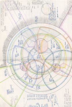
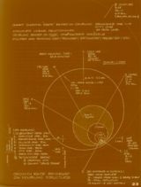
| In
a dome of 50 feet or greater, the interior volume
of the sphere is such that the geometrical options
become very great. |
| This
illustration is a space study for a multi-level combined
home/office and guest complex inside of a 75 foot
dome. |
| It
was conceived for a sloping site - the shaded area
(in the upper left quadrant) is where the dome goes
into the ground (Providing a heat sink). The rest
of the structure completes nearly a full circle above
the lower slope providing views of interest and a
variety of access points to the exterior. |
| Spaces
of great beauty and utility can be built this way.
The exterior shell is one simple statement made of
two elements: one solid and one “open” (glassed).
the interior elements which make up most of the building
do not have to deal with weather. Therefore, they
can be designed to be light and simple - they address
their own minimal structural requirements, and only
have to deal with sight line and arrangement requirements,
storage and acoustics; prospect and refuge. |
| Separating
the shell (environment value) and the complexities
of the interior, gives freedom to both. This a strategy,
by the way, that can successfully be employed with
structures of a more conventional kind. The result
should be integrated - this does not means
the elements have to be connected. |
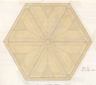
Window
treatment - Snowflake Dome May 1976 |
| Another
generic design issue with domes is the appropriate
treatment of the skylight/windows. In the Snowflake
configuration, all the window areas are in the hexagonal
and pentagonal prefabricated pieces (but not all of
the hex and pent elements, of course). As noted,
these window elements can be placed with great care
- for profound effect, however, there remains a number
of issues: sun control, privacy, night lighting and
the proper framing of the window elements without
complicating the inherent simplicity of the dome
skin. |
 |
| These
configurations provide the ability to place windows
exactly where required - something much more
difficult to achieve in conventional structures. |
|
| The
window treatment design deals with these issues by
creating a valence unit that fits in the interior
of the dome
after
the components are erected. The fixed glass of the
dome is a triangle in each hex segment and is simply
trimmed out as shown. The valence fits into the hex
and slopes inward, toward it’s center, at the
same angle as the dome elements slope outward. Around
the hex perimeter of the Valence, an indirect light
cove is built in that lights up this cavity at night.
This can be supplemented with exterior light poles
as shown on the “addition to a traditional house
Section” (above) and illustrated by the MLU
Dome below. In addition, built into this valence,
is a series of triangular shades that “close” by
pulling into the center (by electric motors). When
open, they expose their tips as shown. This shade
material is both insulating and shading. This careful
combination of lighting and shades creates a number
of options for dealing with light, views, temperature
and privacy. Note that the MLU employs this glassing
strategy and provides a built in ladder for roof
access. |
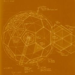
| The
MLU stand for Minimum Living Unit. I explored
this project, in November 1975, as an attempt to
define what could be the minimum cost and maximum
living accommodation that would make up decent, graceful,
affordable adaptable housing and small scale office
and retail units. There was - and remains today -
tremendous gaps in these arenas - gaps that are not
being addressed by conventional architecture-building-financing
institutions. Many prior attempts to use wood and
other accessible means and the geodesic dome have
a spotted record. Funk seems to rule. Some pieces
of great charm have been produced but few of sustaining
architectural quality. |
| To
achieve a better result, a grammar has to be derived
that intrinsically employs the shape of the dome
in a useful way. In addition, a building method has
to be created. I suggest that the boat building industry
has long ago created the tools, practices and components
necessary for this. Small, strong, endurable, beautiful
wooden buildings are possible and they can be produced
in clean, low production, low-scale, shops. Fine
architecture can be produced that is affordable my
millions, that today, have little choice regarding
the quality of their environment. |
| Of
course, it should be clear that a variety of alternative
energy, food growing and waste-management strategies
should be employed with the MLU. These will be documented
elsewhere but have to be understood and an integral
aspect of the idea. The cost of traditional infrastructure
systems is not affordable by affordable housing. |
bootstrap_to_space
innovation_process |
|
 |
| These
projects have intrinsic value in themselves.
There exists other reasons for exploring their virtues,
and the “shell as environment valve” design
strategy, besides that of mobile and low-cost environments
in
today’s Earth-economy. Collaborative
living as illustrated in Domicile [link] and
Mega City [link],
is one. The “Bootstrap
to Space” strategy [link] is
another. |
|
| Innovation
is both evolutionary and discontinuous. What is necessary,
today, is to combine these two - often competing
- approaches into one harmonious method that
integrates present needs and long-term goals. This
is the “Getting HERE from THERE” strategy
that is so intrinsic to the Taylor System and Method. |
| Our
separation of low cost housing from large-scale building,
from transportation, from work habitats, from computer
technology, from our space endeavors, is precisely why we
sub-optimize all of them and fail, again and again,
to get the synergy we need for true advancement.
The division of architects, builders, engineers,
manufactures, developers, from one another further
fuels this problem. Does it really take an army of
organizations - each hostile to one another - to
build a simple dwelling? Is is really efficient to
treat, housing, offices, apartments, commercial structures,
transportation and space units as if they were totally
different arts? I think not. |
| The
biggest barrier to building this way - other than
social indifference - is the way building
is conducted [link] today.
This way-of-working [link] wastes,
at least, 50% of the money spent and 75% of the time
used in non-value-added activities. I demonstrated
this in the 1960s [link].
It has not changed in the last 35 years - in fact,
it has gotten worse. |
| The
purpose of a system is it’s output. Want to
change the result, change the structure of the process
- there is no other way. |
|
 |
| The
EcoSphere Garden Project [link] is
an easy way to get started exploring these ideas.
Easy to build and productive;
it should pay for itself, in produce, within a few
of years. |
|
|
|
| To
MG Taylor Nashville Compound Project |
|
|
Matt
Taylor
Palo Alto
May 19, 1999

SolutionBox
voice of this document:
VISION • STRATEGY • SCHEMATIC
|
|
click on graphic for explanation of SolutionBox |
posted:
May 19, 1999
revised:
January 1, 2003
• 20000513.151824.mt • 20000616.151133.mt •
• 20000621.171330.mt • 20000701.908912.mt •
• 20000702.859134.mt • 20000829.321487.mt •
• 20030102.237761.mt •
note:
this document is about 80% finished
© Matt
Taylor, 1973, 1975. 1976, 1979, 1999, 2000, 2003
Certain
aspects described are Patented and in Patent Pending
IP
Statement and Policy |
|
|